Blower Motor Resistor Operation
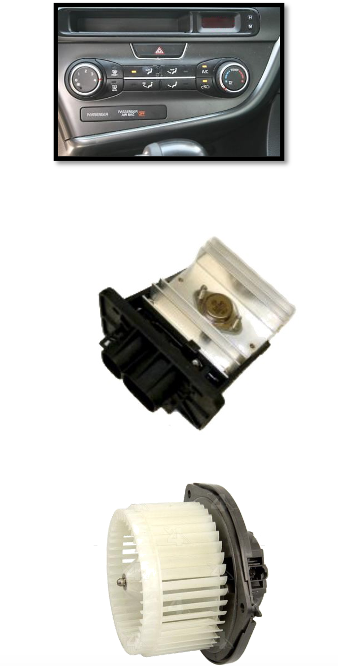
The blower motor resistor is responsible for controlling the blower motor speed. In the past, this was done by varying the voltage supplied to the blower motor. In newer applications, the blower motor resistor is actually a solid state module that sends a varied signal to the blower motor.
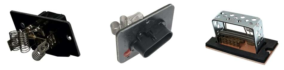
The traditional blower motor resistor is connected to ground and wired in series with the blower motor assembly. Blower motor resistors have several resistors with different resistances. This controls the current that runs through the blower motor. Each fan speed selection is connected to one or more of the resistors in the blower resistor assembly. The change in resistance controls the current through the blower motor, which in turn limits the speed that the blower motor spins at. When high speed is requested, the blower motor resistor is bypassed and the blower motor ground circuit is connected directly to ground. This allows the maximum current through the blower motor and maximum speed occurs.
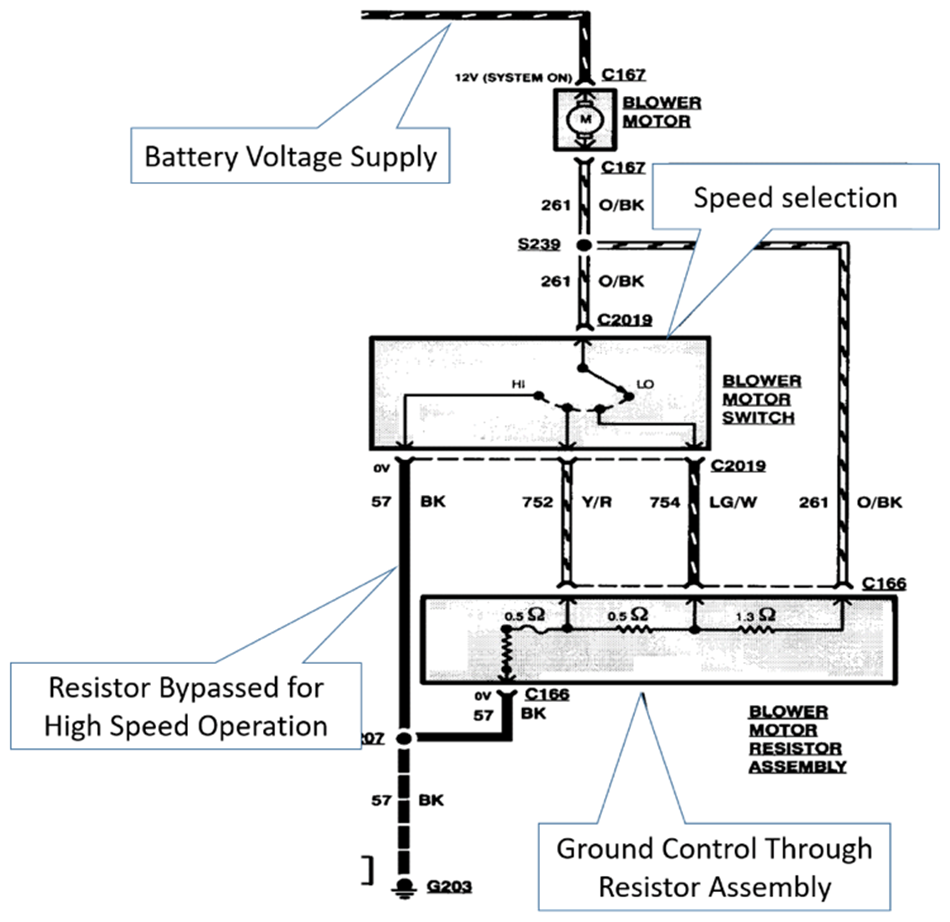
Typical Blower Motor and Resistor Wiring
Reminder - before you start testing, get the wiring diagrams and system operation for the blower motor and resistor for the vehicle application.
Testing Tips
- Use service information to get the specific testing procedures and resistance values for ohm testing the resistor itself.
- Verify power to blower motor
- Verify the main ground to switch and resistor.
- Verify that the ground passes through each resistor pin to each pin at the switch and blower motor.
- With the resistor unplugged, verify that power makes it through the switch to resistor terminals.
Power Tip - The blower motor resistor produces heat when in operation. This is why the resistors are located in the path of the blower motor airflow as it provides the cooling to resistors. If the blower motor is operated with resistor assembly removed from its location, it will likely cause the blower motor resistor to fail. Excessive blower motor amperage due to a faulty blower motor or restricted cabin air filter should also be considered or possibly replaced to prevent repeat failures.
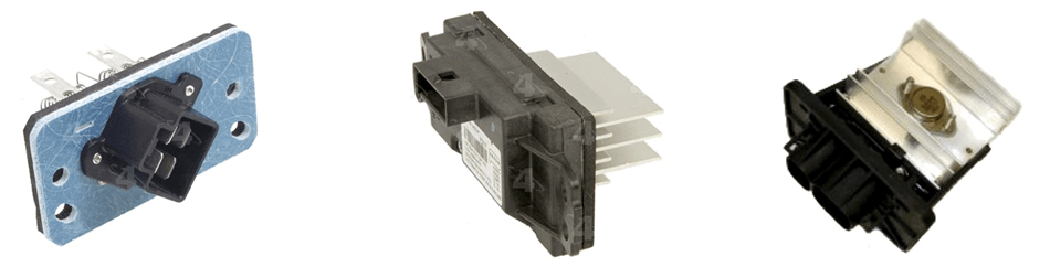
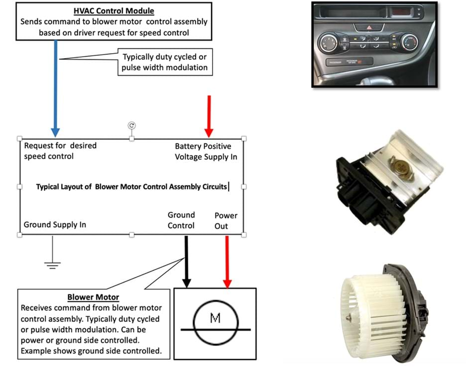
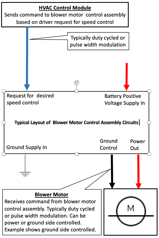
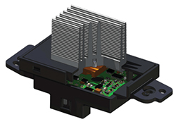
More recently, blower motor speeds are controlled using different methods. Most manufacturers have moved from simple resistor circuits to electronic control modules and solid state controls.
The following guidelines are provided to help in the understanding how blower motor speeds are controlled and testing of blower motor control circuits. It is always recommended to refer to service information for the specific vehicle you are working on.

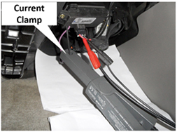
The use an inductive amp clamp to verify that the blower motor current draw is not excessive. Worn out blower motors can cause excessive current. If the current is too high, replace the blower motor. This excessive amperage will cause the new blower motor control assembly to fail again. A guideline number for maximum amperage on high speed is Approximately 15 to 20 amps. Specific vehicle applications information should be verified.
Power Tip – This possible repeat failure typically occurs during testing when we are looking to verify if our diagnosis is correct. It happens when the currently installed or newly to be installed blower motor control assembly is operated without it being completely installed in its proper location. The air flow created by the blower motor past the heat sink is used to help keep the electronic components inside of the blower control assembly from overheating. This failure may occur instantly or create a comeback sometime later.
It is important that there is airflow in the vehicle itself to keep the blower motor control assembly from overheating. Inspection of the cabin air filter should be performed.